الجمعة، 30 أغسطس 2024

Recycle Plastic Bottles Into 3D Printer Filament


Plastic consumption has grown at a tremendous rate over the past two decades as plastics now play an important role in all aspects of modern lifestyle. Plastics are used in the manufacture of numerous products such as protective packaging, lightweight and safety components in cars, mobile phones, insulation materials in buildings, domestic appliances, furniture items, medical devices etc.


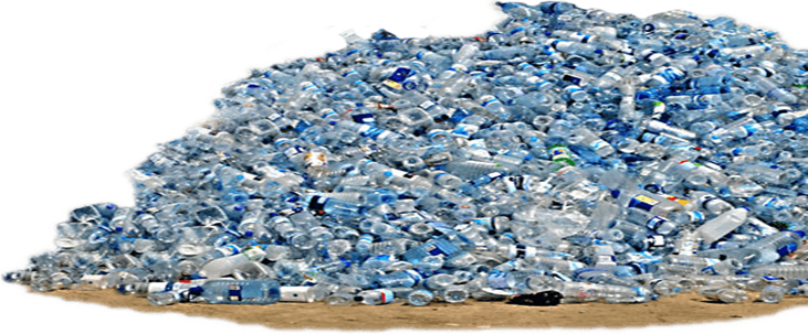
Figure 1Plastic                                                                   


Because plastic does not decompose biologically, the amount of plastic waste in our surroundings is steadily increasing. More than 90% of the articles found on the sea beaches contain plastic. Plastic waste is often the most objectionable kind of litter and will be visible for months in landfill sites without degrading.


Figure 2Plastic.


Dangers of Plastic Bottled Water

Recent years have seen an increase in awareness regarding the negative impact plastic water bottles have on the environment. Unfortunately, while most people know that plastic water bottles are bad for the environment, this awareness has not resulted in a significant drop in the use of disposable water bottles. In fact, their use is still on the increase with Americans using an average of 50 billion plastic water bottles a year; and while recycling is more accessible than ever,  90% of plastic water bottles are not recycled after use, meaning that billions of plastic bottles are entering our landfills, and even our oceans, every year. In fact, so much plastic waste makes it into our oceans that it is estimated that over a million marine animals are killed by plastic waste each year, often due to accidental plastic ingestion.

However, while the environmental effects of disposable water bottles alone should be enough to make us consider purchasing a reusable water bottle and a home water filter, there are also other benefits to be gained by ditching plastic water bottles. While the environmental impact of plastic bottles gets most of the attention, there are also other reasons why you should consider switching to a reusable water bottle. Here is an overview of just a few of the other reasons to go reusable, including some lesser-known dangers of drinking bottled water.


process of Recycle Plastic Bottles Into 3D Printer Filament

Cutting the tape and extrusion happens in two completely separated processes on the same machine. A PET bottle is prepared by cutting off the bottom, and the open rim is pushed between a pair of bearings, where a cutter slices the bottle into one long strip, as a driven spool rolls it up. The spool of tape is then moved to the second stage of the machine, which pulls the tape through a hot end very similar to that on a 3D printer. While most conventional extruders push the plastic through a nozzle with a screw, the Pet Bot only heats up the tape to slightly above its glass transition temperature, which allows the driven spool to slowly pull it through the nozzle without breaking. A fan cools the filament just before it goes onto the spool. The same stepper motor is used for both stages of the process.


We like the simplicity of this machine compared to a conventional screw extruder, but it’s not without trade-offs. Firstly is the limitation of the filament length by the material in a single bottle. Getting longer lengths would involve fusing the tape after cutting, or the filament after extrusion, which is not as simple as it might seem. The process would likely be limited to large soda bottle with smooth exterior surfaces to allow the thickness and width of the tape to be as consistent as possible. We are curious to see the consistency of the filaments shape and diameter, and how sensitive it is to variations in the thickness and width of the tape.

.


Figure 3: plastic bottle inlet

Figure 4: filament outlet.


Dimensions and Costs

When designing the most important step is to estimate the initial dimension that can be done for the design. After that the cost which is also important. Design engineers focus on performance, appearance, and reliability. All-important over cost when making design decisions. But if the idea is expensive and it high costly for the market, engineers find solutions by redesigning and find alternative designs. Figure (9) shows initial dimensions for the machine which is the width is .5 meter and the length is .5 meter. The range of the cost can change depending on the components used and materials. But it approximately between 150 KD to 250 KD.

Figure 5:Expected Final Design. 

component of Recycle Plastic Bottles Into 3D Printer Filament


A.    HARDWARE

Ø  AC power cable (IEC C13)

Ø  AC 08 power socket

Ø  x2 6810 ZZ or 6810 2RS bearing

Ø  x3 608 2RS or 608 ZZ bearing

Ø  E3D STANDARD Volcano hotend

Ø  Silicon sock for hotend

Ø  Volcano nozzle

Ø  Drill 1,7mm / 3,5mm / 5mm

B.    ELECTRONICS

Ø  Mean well LRS-75-12 (100-240V AC)

Ø  PID temperature controller REX-C100FK02-M*AN (100-240V AC) RELAY

C.    OUTPUT

Ø  12V 37D metal gearmotor (30RPM)

Ø  PWM motor controller 5A

Ø  40x40x10 12v fan

Ø  Type K thermocouple

Ø  3D printer heater 12V 40W

D.    SCREWS AND NUTS

Ø  All screws are DIN 912 / ISO 4762

Ø  x2 M3x60 STAINLESS STEEL!

Ø  x10 M3x5

Ø  x1 M3x8

Ø  x40 M3x10

Ø  x8 M3x16

Ø  x14 M4x16

Ø  x1 M8x40

Ø  x4 M3 normal nut DIN 934 / ISO 4032

Ø  x1 M3 nylon locking nut DIN 985 / ISO 10511

References

[1]. Recycling of PET Plastic Bottles | EcoMENA

[2]. PET bottle recycling - Wikipedia

[3]. 5 Types of Plastic are Used in 3D Printing - Thong Guan

[4]. Is There Finally a Machine That Can Turn Plastic Bottles Into 3D Printer Filament? - Hackster.io

[5]. Deceptively Simple Process Turns Bottles Into Filament | Hackaday

[6]. PET Bottle Recycling: Waste to 3D Printing Filament - YouTube [7]. PetBot: Turn PET Bottles Into Filament | Hackaday.

[8]. Significantly Increasing Recycling Efficiency with PET Bottle Labels that Float on Water | Polyplastics Global Website (polyplastics-global.com)

[9]. 3D file PETmachine, make Your own filament from plastic bottles at home!3D print object to downloadCults (cults3d.com)

[10]. PET Bottle Blow Molding Machine, Plastic Machine, Filling Machine - FAYGO (faygounion.com)

[11]. (98) PET-Machine, make Your own 3D printer filament from plastic bottles at home (DIY!) - YouTube


الأحد، 2 يونيو 2024

Alloyed and Unalloyed and their Welding Properties

Structure:

  •  Unalloyed Steel: Primarily composed of iron (Fe) with a small amount of carbon (C) (< 2%). The crystal structure depends on carbon content and temperature. At room temperature, it's ferrite (body-centered cubic), which is relatively soft and ductile.
  • Alloyed Steel: In addition to iron and carbon, these steels have other elements like manganese (Mn), chromium (Cr), nickel (Ni), etc., added to achieve specific properties. Alloying elements can form new crystal structures or modify the existing one, influencing grain size and distribution.

Mechanical Properties:

  • Unalloyed Steel: Generally lower strength and hardness compared to alloyed steels. However, they offer good ductility (ability to deform) and weldability.
  •  Alloyed Steel: Offer a wider range of mechanical properties depending on the alloying elements and heat treatment. They can be high strength, high hardness, or have improved corrosion resistance. However, weldability can be affected by factors like increased hardenability (becoming brittle when cooled rapidly) due to alloying elements.

Welding Considerations:

  •  Unalloyed Steel: Generally easier to weld due to their simple structure and good weldability. However, they may be prone to distortion and cracking if not welded properly.
  • Alloyed Steel: Welding procedures need to be carefully chosen based on the specific alloy composition. Preheating and post-heating techniques might be required to control cooling rates and prevent cracking. Some alloy steels may require special filler metals to match the properties of the base metal.

Non-ferrous Materials used in Welding

These materials have different properties and require specific welding techniques compared to steel. Here are some common examples:
  • Aluminum (Al): High electrical conductivity, lightweight, but susceptible to oxidation during welding. Requires inert gas shielding to prevent oxide formation.
  • Stainless Steel: An alloy steel with chromium content that provides good corrosion resistance. However, certain types of stainless steel can become brittle during welding due to chromium carbide precipitation.
  •  Copper (Cu): Excellent conductor of heat and electricity, but can be prone to hot cracking during welding. Special techniques like oxy-fuel welding or inert gas brazing are often used.
  • Nickel (Ni): Offers good corrosion resistance and high strength. However, welding can be challenging due to high melting point and susceptibility to cracking.
  •  Titanium (Ti): High strength-to-weight ratio and excellent corrosion resistance. Requires inert gas shielding and careful control of heat input to prevent embrittlement.

Types of Forces and Loadings

  • Tensile Forces: These pull the joint apart, trying to separate the welded pieces. This is the most common type of force for many structures like beams and trusses.
  • Compressive Forces: These push the welded pieces together. While generally less critical than tensile forces, excessive compression can still cause buckling or crushing of the material.
  • Shear Forces: These act parallel to the weld interface, trying to slide one piece of metal over the other. This can occur in beams subjected to bending or in bolted connections where the weld transfers the shear force.
  • Torsional Forces: These twist the welded joint, putting the weld in a combination of tension and shear stress. This is common in shafts or axles that transmit rotational power.

Effects of Forces and Loadings:

  • Stress Concentration: Welds can introduce localized areas of high stress compared to the base metal. This is due to the slightly different properties of the weld metal and the abrupt change in geometry. The magnitude of the force and the type of loading will determine the stress level in the weld.
  • Deformation: Under load, the welded joint may deform elastically (springing back) or plastically (permanently bending). The amount of deformation depends on the material properties, the weld quality, and the magnitude of the force. Excessive deformation can lead to joint failure.
  • Fatigue: Repeated loading and unloading cycles can cause fatigue cracks to initiate and propagate in the weld or the heat-affected zone (HAZ) around the weld. This is a major concern for structures like bridges or machinery that experience cyclic loading.
  • Residual Stresses: The welding process itself can introduce residual stresses in the joint and surrounding metal. These stresses are internal and can be tensile or compressive. They can interact with the applied stresses and affect the overall strength and fatigue life of the joint.

Explain the defects and irregularities

  • Cracking in Steel:
o Hot cracks: Develop during the solidification of the weld pool due to shrinkage stresses. More common in high-carbon and alloy steels due to their hardenability.
o Cold cracks: Form after welding has completed, typically in the Heat Affected Zone (HAZ) due to residual stresses and hydrogen embrittlement.
  • Cracking in Non-ferrous Materials:
o Aluminum: Prone to cracking due to solidification shrinkage and hydrogen entrapment.
o Magnesium: Highly susceptible to cracking due to rapid oxidation and moisture absorption.
o Nickel: Cracking can occur due to high residual stresses and improper welding techniques.

  • Porosity: Small gas bubbles trapped within the weld metal. Caused by improper shielding gas, moisture, or contaminants on the base metal. Weakens the joint and can be a pathway for corrosion.
  • Incomplete Fusion: Lack of complete melting and bonding between the weld metal and base metal. Can occur due to insufficient heat input, improper joint preparation, or incorrect welding technique. Leads to a weak and leaky joint.
  • Undercut: A groove melted into the base metal adjacent to the weld bead. Caused by excessive heat input or improper torch angle. Reduces the effective cross-sectional area of the joint and can lead to stress concentration.
  • Overcut: Excessive melting of the base metal beyond the intended weld zone. Similar causes to undercut, but can also occur due to incorrect torch manipulation. Weakens the joint and may expose susceptible base metal to corrosion.
  • Slag Inclusions: Non-metallic trapped oxides, fluxes, or other debris within the weld metal. Reduce joint strength, ductility, and can promote corrosion.
  • Warping and Distortion: The heat of welding can cause the base metal to expand and contract unevenly, leading to warping and distortion of the workpiece. This can be a cosmetic issue or create problems with fit-up for subsequent assembly.
  • Material Property Changes: The high temperatures involved in welding can alter the microstructure and mechanical properties of the base metal in the HAZ. This can make the HAZ harder and more brittle, potentially affecting the overall strength and toughness of the joint.

Factors Affecting Defect Formation:

  • Material properties: Alloying elements, carbon content, and presence of impurities can influence susceptibility to cracking and other defects.
  • Welding process: The type of welding process, heat input, and travel speed play a crucial role in defect formation.
  • Welding technique: Improper torch angle, travel speed, and cleaning procedures can significantly impact weld quality.
  • Environmental factors: Wind, moisture, and contamination in the surrounding air can affect shielding gas effectiveness and promote porosity or oxidation.

Preventing Defects:

  1.  Choosing the right welding process and filler metal for the specific material being welded.
  2. Proper joint preparation to ensure good fit-up and cleaning of surfaces before welding.
  3. Maintaining proper welding parameters like heat input and travel speed.
  4.  Using appropriate shielding gas to protect the molten weld pool from contamination.
  5. Preheating and post-weld heat treatment may be necessary for some materials to control cooling rates and reduce residual stresses.
  6. Visual inspection and Non-Destructive Testing (NDT) techniques like X-ray or ultrasound to detect defects after welding.

Analysis of Materials Used in Welding Processes

Alloyed and Unalloyed Steel:
Structure:
  •  Unalloyed Steel: Primarily iron (Fe) with low carbon content (<2%). At room temperature, the structure is ferrite (soft and ductile).
  • Alloyed Steel: Contain additional elements like chromium (Cr), nickel (Ni), etc., which create new crystal structures or modify existing ones, affecting grain size and distribution.
Mechanical Properties:
Unalloyed Steel: Generally lower strength and hardness but offer good ductility and weldability.
Alloyed Steel: Offer a wider range of properties depending on the alloying elements. They can be high strength, high hardness, or have improved corrosion resistance. However, weldability can be affected due to factors like increased hardenability.

Welding Considerations:

  •  Unalloyed Steel: Generally easier to weld due to their simple structure. However, they are prone to distortion and cracking if not welded properly.
  •  Alloyed Steel: Welding procedures require careful selection based on the specific alloy. Preheating and post-heating techniques might be needed to control cooling rates and prevent cracking. Specific filler metals may be required to match base metal properties.

Effects of Irregularities and Forces:

  • Irregularities: Defects like cracks, porosity, incomplete fusion, undercut, and slag inclusions weaken the joint and act as stress concentration points. These can occur due to improper welding techniques, material contamination, or unsuitable welding parameters.

Forces and Loading:

  •  Tensile Forces: Pull the joint apart, making the weld susceptible to cracking.
  •  Compressive Forces: Generally less critical, but excessive compression can cause buckling or crushing.
  • Shear Forces: Can cause the joint to slide, and the weld experiences a combination of tension and shear stress.
  • Torsional Forces: Twist the joint, putting the weld under combined tension and shear stress.

Non-Ferrous Materials:

  •  Aluminum: Lightweight and good conductor, but susceptible to oxidation during welding. Requires inert gas shielding to prevent oxide formation.
  • Stainless Steel: Offers good corrosion resistance, but some types can become brittle due to chromium carbide precipitation during welding.
  • Copper: Excellent conductor, but prone to hot cracking. Requires specific techniques like oxy-fuel welding or inert gas brazing.
  • Nickel: Offers good corrosion resistance and high strength, but welding can be challenging due to high melting point and susceptibility to cracking.
  • Titanium: High strength-to-weight ratio and excellent corrosion resistance. Requires inert gas shielding and careful heat input control to prevent embrittlement.

Destructive Testing:


Figure(1)
  • Tensile Testing: A welded joint is pulled apart under controlled force to measure its breaking strength and identify weaknesses. This can reveal defects like incomplete fusion or cracks.
  • Bend Testing: The welded joint is bent to a specific angle to assess its ductility and identify cracks or other defects that may cause premature failure under bending stress.
  • Metallography: A small section of the weld is cut, polished, and examined under a microscope to reveal the microstructure of the weld metal and heat-affected zone (HAZ). This can identify defects like porosity, cracks, or improper grain structure.

Non-Destructive Testing (NDT):


Figure(2)
  • Visual Inspection: The most basic method, using the naked eye or with magnifying tools, to identify surface defects like cracks, undercuts, or excessive spatter.
  • Radiographic Testing (X-ray): X-rays are passed through the weld, and the resulting image on film reveals internal defects like cracks, porosity, or incomplete fusion.
  • Ultrasonic Testing: High-frequency sound waves are transmitted through the weld, and reflections from defects are detected. This method can locate cracks, voids, and other internal defects.
  • Magnetic Particle Testing: A magnetic field is applied to the weld, and magnetic particles are sprinkled on the surface. These particles are attracted to areas of leakage in the magnetic field, which can indicate cracks or other defects.
  • Liquid Penetrant Testing: A liquid penetrant is applied to the weld surface, allowed to seep into cracks, and then cleaned off. A developer is then applied, drawing the penetrant out of the cracks, making them visible under ultraviolet light.

الخميس، 18 أغسطس 2022


Wireless Humanoid Bionic Arm on Robotic Vehicle


 This system has two wireless controllers mounted on gloves, one for each hand of the operator. Here system precisely replicates the finger motion of one hand of the operator onto the motion of the humanoid arm. The RF receiver is interfaced with microcontroller to control the driver IC which is responsible for controlling the movement of the arm. The transmitter circuit consists of an accelerometer sensor which is interfaced to atmega microcontroller. This transmitter circuit sends commands to the receiver circuit which indicates whether to move the robotic arm in any directions or whether to grip an object or release it. Also using the hand gestures of the other hand of the operator, motion of robotic vehicle is controlled.

Block Diagram


Hardware Specifications 

• At mega Microcontroller 

• Accelerometer &  Gyroyro sensor  

• RF Tx Rx 

 • Bluetooth Modul

• Finger Motion Sensor Gloven Finger Motion Sensor Glove

 •Resistors 

• Capacitors

 • Transistors

 • Cables and Connectors Cables and Connectors 

• Diodes

Software Specifications 

• Arduino Compiler 

 •  CMC Programming Language: C

ATmega328

 The Atmel 8 bit bit AVR RISC based microcontroller combines based microcontroller combines 32KB ISP flash memory with read memory with read  while write capabilities, 1write capabilities, 1 KB EEPROM 22 KB SRAM 23 general purpose I/O lines, 32 general purpose , 23 general purpose I/O lines  32 general purpose working  registers , three flexible timer/, three flexible timer/counter  with compare modes, internal with compare modes, internal and  external interrupts , serial programmable, serial programmable USART, a byte, a byte--oriented 2oriented 2--wire wire serial interface , SPI serial port, 6 serial port, 6 channel 10channel 10 bit convA/D converter(8(8 channels channels in  TQFP and QFN/MLF packages), programmable packages), programmable watchdog timer watchdog timer with with internal   oscillator  , and five software selectable power saving modes. The , and five software selectable power saving modes. The device operates between 1.8device operates between 1.8--5.5 volts. The 5.5 volts. The device  achieves throughputs eves throughputs approaching 1approaching 1 MIPS per MHz.

Features

High Performance, Low Power AVR® 8--Bit Microcontroller Bit Microcontroller

– Advanced RISC Arch Advanced RISC Architecture itecture

– 131 Powerful Instructions 131 Powerful Instructions

– Most Single Clock Cycle Execution Most Single Clock Cycle Execution

– 32 x 8 General Purpose Working Registers 32 x 8 General Purpose Working Registers

– Fully Static Operation Fully Static Operation

– Up to 20 MIPS Throughput at 20 MHz Up to 20 MIPS Throughput at 20 MHz

–On--chip 2chip 2--cycle Multiplicycle Multiplieerr

Flash Program Memory: 32 k bytes

EEPROM Data Memory: a Memory: 1 k bytes 

SRAM Data Memory: 2 k byte

I/O Pins: 23

Timers: Two 8--bit / One 16bit / One 16--bit 

A/D Converter: 10--bit Six Channel bit Six Channel

PWM: Six Channels

RTC: Yes with Separate Oscillator

MSSP: SPI and I²C Master and Slave Support

USART: Yes

External Oscillator: up to 20MHz


Recycle Plastic Bottles Into 3D Printer Filament   Plastic consumption has grown at a tremendous rate over the past two decades as p...